
TAVI, just like any structural heart disease intervention, relies on effective imaging earlier, throughout, and after the procedure. Imaging’s role in percutaneous valve replacement is comparable to that of appropriate exposure and visualisation in open surgical valve replacement. Visualisation improves the speed, safety, and predictability of the procedure. In addition, imaging throughout the procedure is critical for detecting, avoiding, and treating problems.
Types of available Imaging’s
X- Ray Imaging
Ultra Sound Imaging
Fluoroscopy is the core component of imaging in the cardiac catheterization laboratory. It enables precise viewing of radiopaque structures with high temporal and spatial resolution, which is particularly important for mobile cardiac structures. Fluoroscopy, on the other hand, cannot be used to visualise non-radiopaque structures such as arteries and non-calcified valves.
X-rays often provide a two-dimensional (2-D) image. Unless imaging is done with Biplane, three-dimensional reconstruction is impossible. Fluoroscopic imaging provides a clear view of the devices, allowing for proper and safe manipulation. Trying to visualize images in more than one plane and seeing the response to torquing the device in the same projection is used to generate the device’s orientation in space.
RAO (right anterior oblique) projection provides for anterior–posterior separation, whereas LAO (left anterior oblique) projection allows for left–right separation. Orientation in space can be aided by rotating the device clockwise or counter clockwise to determine if it rotates anteriorly or posteriorly.
Intra-OP Imagine During TAVI, the cornerstone of ultrasound imaging is transoesophageal echocardiography (TEE). Intracardiac echocardiography (ICE), on the other hand, is fast gaining ground and may soon be the ultrasound imaging modality of choice for aortic valve replacement. 2-D TEE provides for tomographic imaging of the heart with high temporal and spatial resolution, allowing for the detection of echogenic structures.
Anatomical imaging of the valves, aorta, and cardiac chambers provides the “eye” to the interventional procedures. TEE and echocardiogram have a lot of limitations, with calcium being the most significant hindrance to ultrasound imaging. Accurate measurements and visibility of the anatomy are compromised by aortic wall or valvular calcification.
ICE imaging has clear advantages in terms of procedural convenience and image control by a single operator. With ICE imaging, the aortic valve may be seen clearly in both the longitudinal and horizontal planes. ICE imaging has a number of drawbacks. ICE probe is still not ideal for measuring left ventricular wall motion and mitral valve function (MV). Although ICE echocardiographic interrogation is not always necessary, it can be helpful in the event of a problem. Furthermore, adjustment of the probe may result in transient pacing wire displacement.
X-Ray Imaging
The first and most important condition for a successful percutaneous aortic valve intervention is anatomic delineation of the left ventricle, aortic valve, coronary arteries, ascending aorta, aortic arch, abdominal aorta, pelvic arteries, and femoral arteries. If possible, a biplane examination of the anatomy is generally the best way to reduce Contrast load and procedure duration.
Left Ventricle Imaging
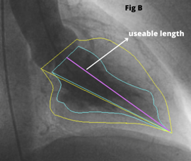
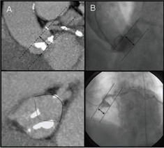
During TAVI an LV Angiogram can be used to determine the size of the left ventricular cavity and the relationship of the left ventricular outflow tract (LVOT) to the ascending aorta. The RAO image [Fig 1A] helps in examining the “useable length” of the LV cavity from the aortic valve to the apex. Place the stiff (Fig 1C) wire at the lateral part of the apex to optimize the ventricle’s useful length for better understanding.
The LAO view [Fig 1B] allows to see the left ventricle’s lateral span as well as the angle of entry from the ascending aorta to the LVOT. If the guide wire can be comfortably put in the ventricle with a good loop, LV angiography is not required. A small hand injection in the left ventricle with a pigtail inserted close to the apex can provide very important information if there is any uncertainty.


Aortic Valve Imaging
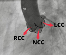
Aortic valve comprised of the leaflets, annulus, and sinuses to the Sino-tubular (ST) junction. Understanding the plane of the aortic orifice requires visualising each sinus. 30 – 40 Degrees of LAO view best visualise left coronary cusp (LCC) to the left whereas the right coronary cusp (RCC) and non-coronary cusps (NCC) are overlapped to the right half of the aortic diameter [Fig. 2].
Aorta is slanted such that the NCC is usually the lowest sinus. The LAO Cranial (30-40 & 20 Cranial) angulation permits the fluoroscopic plane to be aligned with the aortic orifice. Angle can be modified until the bottom of NCC aligns perfectly with the bottom of RCC in this view.
The RCC is in the front and the NCC is at the back in RAO projection. [Fig. 3 (C)] The LCC covers both of these leaflets, but mostly the NCC. In this view, the LCC is higher than the RCC and NCC due to the aorta’s inclination. RAO Caudal angulation (30-45 RAO & 20 Caudal) can help to make the X-ray beam parallel to the aortic orifice.
The motion of each cusp is vital to appreciate since it aids in crossing the valve in a systematic manner and also identifies the exact position of calcification when the coronaries, annulus, and leaflets are all calcified. The degree of calcification should be determined with care.
In the LAO view, the mitral annular calcification usually extends from the region of the annulus that supports the LCC and the NCC. The pattern of calcification may be a key factor in determining stent/frame apposition and paravalvular leak. Sino Tubular junction calcification is yet another important factor that needs to be analysed before the procedure (Fig. 4).

Coronary Artery Imaging
The origins of the left and right coronary arteries should be examined thoroughly. In the LAO cranial view, the height of the LCA origin can be determined (Fig. 5). It’s also worthy to note the origin’s position in reference to the aortic commissures. The RAO view may be used to assess this, however, CT and TEE make it easier to determine. Although no RCA compromise has been detected as a result of valve deployment, a comprehensive examination of its origin and height is required.
Aorta Imaging
The angle formed by the ascending aorta and the LVOT determines the ease with which the aortic valve can be crossed. The most significant angle is the LAO angle, but RAO angulation is also important. The wire, as it sits across the aortic valve, clearly defines the direction with which the device will take as it crosses the aortic valve.
Another location where the system can have significant slack is the horizontal length of the arch, which can cause motion during the key step of valve deployment. For atraumatic manipulation of these massive devices in the aorta, calcification of the ascending aorta and arch arteries requires particular attention.
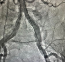
During pre-procedure evaluation, the anatomy of the descending aorta, pelvic bifurcation, and ileo-femoral system should be carefully assessed. Femoral puncture site must be in the common femoral artery before the bifurcation but below the inferior epigastric artery (Fig. 6). It is possible to avoid calcified plaque by examining the puncture site using fluoroscopy or ultrasound.
The tortuosity and its interaction with the wires and sheath should be carefully observed. The angle and calcification of the aortic bifurcation should be examined to estimate how the big sheath will sit in relation to the aortic wall.
On table Imaging
Crossing of Aortic Valve
This process is primarily performed using fluoroscopy. An Amplatz Left-1 catheter and a straight hydrophilic 0.035in wire is routinely used to cross the aortic valve. The LAO projection is the ideal because it shows the coronary ostia and the aortic orifice clearly. In systole, the wire is progressively advanced out of the catheter. If the wire bends to the left, the catheter is most likely sending it to the LCC, and counter-clock rotation of the catheter will guide it to the centre.
If the wire moves to the right, it may be in NCC or RCC seen well in RAO view, in which case clocking or counter-clocking will redirect the wire to the centre. By adjusting the catheter’s height, you can change the trajectory and make it easier to cross.
When the right and left leaflets are immovable and the orifice is oriented anteriorly (as seen in bicuspid valves), the RAO view is useful. In some individuals, a supra-aortic angiography may be required to further identify the anatomy, particularly if the anatomy is changed or deformed.
Balloon Aortic Valvuloplasty (BAV)
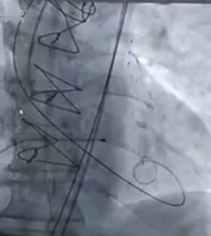
Once the aortic valve is crossed, hydrophilic wire is exchanged with Stiff 0.035in wire in the left ventricle. During BAV or valve deployment, proper wire location is critical to avoid complications such as MV damage or LV perforation. A gentle loop in the stiff wire (3 or 6 cm floppy guidewire) at the transition prevents ventricular ectopy and offers support to keep the devices from damaging the left ventricle.(Fig 7A)
Before positioning balloon for BAV, It is important to confirm the temporary pacing lead at position by fluoroscopy with suitable pacing parameters.
After careful selection of appropriate balloon size, which suits with measured annulus size. The Balloon Is advanced and positioned at the level of Aortic valve (Fig 7B) . All steps must be carefully monitored under fluoroscopy. Once everything is fine balloon need to inflated under fluoroscopy with rapid RV pacing. After BAV, the severity of aortic regurgitation should be assessed with TEE and hemodynamic changes (hypotension, decline in aortic diastolic pressure, and raise in LV end-diastolic pressure) must be monitored.

Introduction of the Sheath
Under fluoroscopic guidance, serial dilations should be performed. During the introduction of dilators, careful monitoring of the arteries and aorta can allow identifying how much force can be safely given. The sheath is placed under fluoroscopic guidance while the wire’s positioned in the left ventricle.
Advancement of The TAVI Valve
The valve is introduced in the sheath, cautiously without accidentally advancing the sheath. Fluoroscopy is used to monitor valve exit to ensure that the valve does not damage the aorta wall as it exits the sheath. Fluoro imaging prevents the device from colliding with the wall or calcifying plaques in the arch.
Crossing of The TAVI Valve
A careful eye on the wire permits enough tension to be applied to give adequate rail. The wire should not be withdrawn from the left ventricle unless absolutely necessary. The device is subsequently inserted into the aortic orifice, with fluoroscopic and imaging confirmation of appropriate location.
Positioning of The TAVI Valve
Edwards Prosthetic Valve
Because the valve is not repositionable, this is the most important step in percutaneous aortic valve replacement with the current technique. Depending on the size of the valve, the stent is 14 to 16 mm long. Prior to balloon inflation, the stent is positioned so that 60% of the stent is ventricular and 40% is aortic. Due to its great rigidity, the valve tends to follow the ascending aorta into the ventricle and does not confirm to the curve. In situations where ascending aorta makes a sharp angle with LVOT, the stent will be at a steep angle in the aortic orifice.
In this scenario, there will be “realignment movement” of the valve as balloon inflation brings the system in the centre of the aortic orifice. Because the valve moves from posterior to anterior and right to left as it centers itself, this motion often moves the stent in the aortic direction in transfemoral patients. As a result, in patients with a horizontal ascending aorta, a slightly ventricular position is acceptable.
It’s also crucial to make sure the stent’s aortic edge reaches the tip of the aortic leaflets to avoid the native leaflets overhanging the stent, which might induce severe aortic regurgitation by preventing the prosthetic valve leaflets from closing properly.
Aortic root injection is done with 5 to 10 cc contrast, injected with pressure or hand injection within 0.8 seconds. In patients with compromised renal function, the patient’s kidney function should be considered, and contrast load should be reduced. To ensure that the appropriate position is achieved, rapid pacing, breath holding, and root injection are extremely beneficial.
Although fluoroscopy is used for the proper positioning, echocardiographic evaluation is also required to confirm the fluoroscopic findings. TEE or ICE are used to study the relationship between the stent’s aortic edge and the valve tips. On TEE, the angle of the prosthetic valve to the LVOT is clearly visible, whereas ICE does not. The short-axis image of the aortic valve can clarify whether the valve is crossing centrally or eccentrically. Echocardiography can also be used to detect stent movement during pacing or breath-hold. It is reasonable to measure the length of the stent to ensure that the edge identification is accurate.
Evaluation of Valve Performance
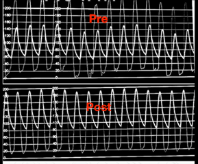
After valve deployment, sufficient hemodynamic recovery is the most essential measure of success. The aortic pressure waveform, as well as systolic and diastolic blood pressures, provide the most important information on valve performance. Echocardiography and fluoroscopy are used to confirm the valve’s proper placement and deployment. When the valve is properly sized and deployed, there is usually some flaring of the stent’s ends.
Removal of Sheath
The removal of the sheath and achieving hemostasis is the next critical step. If there is any doubt that the vessel has been injured, perform contralateral angiography while the sheath is being removed. Rupture or major dissections of the iliac arteries must be discovered quickly in order to receive prompt treatment.
IMAGING TO FIND COMPLICATIONS
Finding and treating complications is one the most significant aspects of the procedural imaging. When attempting to cross the aortic valve, cardiac perforation and ascending aortic dissection are common. Soon after aortic valve deployment, left main occlusion and aortic regurgitation are frequent, while severe Aortic stenosis after aortic valvuloplasty is also possible. Trauma to the aorta and iliac arteries occurs during sheath insertion, however it is not noticeable until the sheath is removed.
You May also Interested: