

Catheter ablation for atrial fibrillation is becoming more common and is increasing in popularity around the world. Since pulmonary vein isolation has remained the foundation of atrial fibrillation ablation procedures, imaging and visualization technologies, as well as energy sources and energy delivery systems, have advanced significantly.
To get good and safe results, you must have a solid understanding of the signals from the pulmonary veins that are picked up by circumferential mapping catheters.
Most of the time, atrial fibrillation starts in the pulmonary veins, which have some very interesting electrical and conduction properties. Understanding pulmonary vein electrical activity allows the source of atrial fibrillation to be eliminated logically and with a clearly defined end-point.
EP recording and pacing systems
Recording systems consist of amplifiers, junction boxes, pulse generators, and monitors that are paired to stimulators. The junction boxes receive signals from the ablation catheters in the heart and send them to the amplifiers. Most recording systems allow the operator to adjust the amplitude and filters of the signal for display, and it is also possible to display up to 64 channels.
The recording system is connected to a stimulator, which lets the operator send timed electrical stimulation to the heart through a pulse generator connected to the mapping and ablation catheters. Prucka, EPMed, Bard, and other manufacturers make EP recording systems.
Recording Settings For Atrial Fibrillation Ablation
During AF ablation procedures, a 12-lead surface ECG and a bipolar endocardial EGM are continuously monitored and recorded with an amplifier and recording system. All intracardiac signals are sampled at 1 kHz, with filter settings ranging from 30 to 250 Hz for intracardiac signals and 0.1 to 50 Hz for surface electrocardiograms.
Intracardiac Signals Amplification and gain of the recordings:
• Circular mapping catheter: 0.2 mV/cm and gain of x8
• RF catheter: 0.1 mV/cm and gain of x16
• CS catheter: 0.2 mV/cm and gain of x8
Unless otherwise specified, the recording speed is 100 mm/sec.
Some centers also use the recording’s amplitude:
• 0.45 mV/cm for the circular mapping catheter
• 0.115 mV/cm for RF catheter
• 0.45 mV/cm for CS catheter
Catheters and sheaths
To map the PV perimeter during PVI, a 10-pole, 20 mm circular or Variable Lasso catheter is advanced through a transeptal sheath (SL-0, St. Jude) and positioned just distal to the PV ostia. An open irrigated tip ablation catheter with an F-curve is used; however, the size of the curve used should be determined by the size of the atrium.
Circular Mapping Catheter
Fixed Loop (10 Poles)
Fluoroscopic images (AP view) are used to view the location of (10 poles) circular mapping catheter electrodes. The distal end of the loop (tip) is electrode 1, and the proximal end is electrode 10. (shaft).
The catheter shaft is usually positioned at the top of the vein when mapping the PV. In this position, during right PV mapping, electrodes 1 to 5 are posterior, and electrodes 6 to 10 are in the anterior portion of the vein.
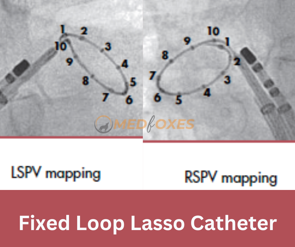
In the case of left PV mapping, electrodes 1 to 5 are anterior, and electrodes 6 to 10 are in the vein’s posterior.
Variable Loop (20 Poles)
AP View Fluoroscopic images are used to visualize the location of variable-loop (20-pole) circular mapping catheter electrodes. Some centers use a 20-pole catheter to achieve sharper signals and better differentiation between PV potentials and far-field atrial activity.
When varying PV size or the common ostium is observed, a variable catheter is advantageous because PVs can be isolated using only one circular mapping catheter. When the circular catheter is fully expanded, the variable loop catheter allows for better contact and stability at the ostium of the PV. This makes the catheter a bit too big.

When mapping the PVs with a catheter with a variable loop, the catheter shaft is usually in the posterior or at the top of the vein. When electrode bi-poles are not fully expanded, they can overlap and cause contact signal artifacts and signal repetition.
Potential Sources of Far-Field Electrograms
This picture shows what could be causing the far-field electrograms picked up by the circular mapping catheter during PV mapping.
The differential diagnosis of far-field potentials for right-sided PVs includes the right atrial myocardium, superior vena cava, ipsilateral PV, and posterior LA.

For far-field potentials on the left side, the LAA, the LA myocardium, the ipsilateral PV, the Marshall vein, and the left ventricle are all possible causes.
Radiofrequency Setup
Radiofrequency energy is delivered at power levels ranging from 25 to 40 watts. 30–40 W on the anterior and 25–30 W on the posterior. These power settings were empirically determined to produce effective lesions while minimizing the risks of PV stenosis, steam pops, cardiac tamponade, and collateral damage to the phrenic nerve, oesophagus, and circumflex coronary artery.
Target temperatures of 40-42 C are achieved (maximum temperature 45 C) by manual titration of irrigation rates from 5-30 ml/minute
Posterior wall ablation should be carefully monitored with Oesophagus temperature probe, 2-5 degree raise in temperature during ablation should be considered as significant and ablation must be stopped immediately
Read Also: 3-Dimensional Rotational Angiography an Imaging Tool in Atrial Fibrillation Ablation