

Based on the understanding of the atrial fibrillation initiation mechanism by focal discharges in the pulmonary veins, focal ablation appeared to be a less effective ablative technique than electrical disconnection at the PV ostium. The unpredictability, inconsistent inducibility, and risk of repeatedly inducing AF during the procedure limit ablation guided by mapping focal ectopy, which has a low long-term success rate and a high recurrence rate. Additionally, the emergence of numerous AF triggers and the high rate of recurrence support a more comprehensive and detailed ablation strategy.
Pulmonary vein isolation has been introduced to solve these problems. PV potentials recognize muscular sleeves that extend from the LA in the PVs. Theses muscular bands are capable of transmitting triggering impulses from pulmonary vein to the LA.
The myocardial fibers that envelope the PVs may be present all along the entire circumference of the PV ostia. Therefore, it may not be necessary to ablate the ostium’s entire circumference in order to stop conduction into and out of a PV
Instead, ablation can be targeted to the segments of the ostium at which muscle fibres are present, which typically involves RF ablation for 30% to 80% of the circumference of the PVs. High frequency depolarizations, which are an indicator of PV muscle potentials, are present at these locations.
The main advantages of this method are that it doesn’t require careful mapping of all PV foci, it has a clear endpoint for ablation even when there are no spontaneous arrhythmias, and the chance of PV stenosis is much lower, though it can still happen.
LSPV Mapping
Positioning the Circular Mapping Catheter (Lasso)
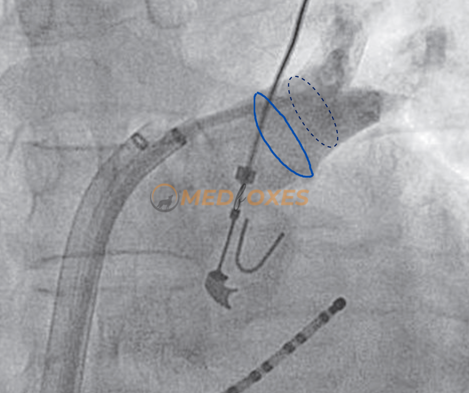
Angiography can be done to locate the ostium of the pulmonary vein and to rule out any pre-existing narrowing. Pre-existing narrowing may be the result of previous ablation or may occur spontaneously as a result of external compression by the aorta or pulmonary arteries during development and growth. If there is any pre-existing narrowing of the pulmonary vein, power should be titrated low.
The Circular Mapping Catheter (Lasso) must be inserted proximally into the vein (Fig-a, Blue circle in the image). The Black dashed circle shows the usual position of a fixed loop lasso catheter. A variable loop lasso catheter helps achieve a more proximal position (Blue circle), as the loop size can be adjusted to approximate the ostium with grip.
Applying RF delivery close to the circular mapping catheter, at the ostium, or at the vein’s antrum is recommended. The anterior wall of left-side veins will usually need minimal encroachment into the vein It is virtually impossible to ablate the ridge between the LAA and the left veins unless this ridge is unusually thick and an intracardiac echo (ICE) is needed to confirm real-time catheter position.
Sinus Rhythm and CS Pacing
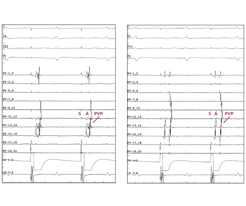
The below tracing (fig-b) explains the utility of coronary sinus pacing during left PV mapping. On the left side, the tracing shows sinus rhythm, and it is difficult to differentiate between PV potentials and LA far-field signals due to simultaneous activation (Blue Circle). On the right side, the tracing shows distal CS pacing, which induced asynchronous activation. The pacing artefact is followed by atrial far-field potentials from LAA, and then PV potentials.

Circular Mapping Catheter Differential Positioning
These tracings (Fig-c) show how different placements of the circular mapping catheter can be used to tell the difference between atrial far-field signals and PVP.
PVPs exhibit progressive temporal delay when traced from PV ostium distally within the PV during sinus rhythm or CS pacing because the PVs are an electrical dead-end (i.e., proximal-to-distal activation). In contrast, as the circular mapping catheter is moved farther distally within the vein, there are no alterations in the timing of the atrial far-field potentials.
On the left image, during CS pacing, the lasso catheter is placed proximally at the ostium of the LSPV. On the right image, the lasso catheter is positioned more distally within the LSPV. When comparing, the proximal position timing of the atrial far-field signals (A) is unchanged; however, the PVPs are recorded with a delay, showing a greater separation between the atrial far-field signals (A) and PVP.
Concealed Pulmonary Vein Ectopy
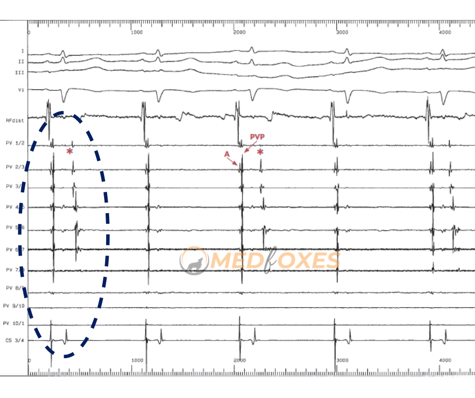
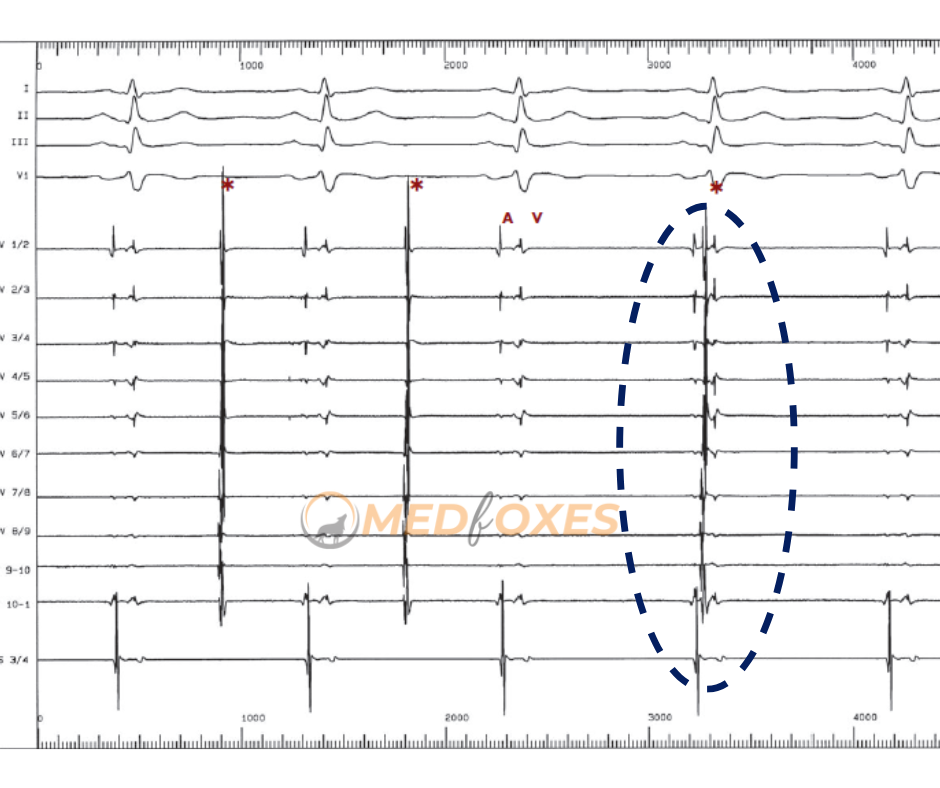
Below (Fig-d), the LSPV tracing shows the activation of the PV potential during sinus rhythm. This is different from the activation of the atria because it happens later.
Late PV potential is more common in fibrillating atriums than it is in normal ones. Note that the concealed PV ectopy (i.e., not conducted to the atrium) occurs every 2 beats (asterisks).
The ability of a vein to cause arrhythmia is “proven in principle” by concealed PV ectopy, which is just as valuable as conducted ectopy as an indicator of arrhythmogenicity.
Concealed PV Ectopy and CS Pacing
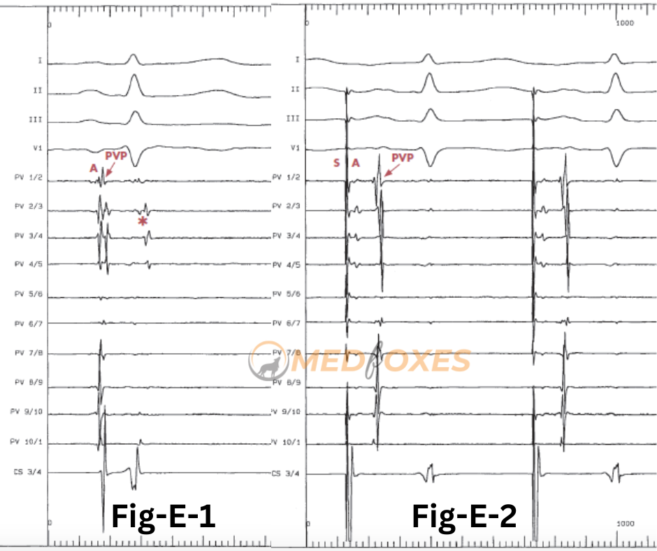
Tracing (Fig. E- 1) from LSPV shows concealed PV ectopy recorded during the sinus rhythm(asterisk), which is in synchrony with the QRS complex on the surface ECG and disappears during CS pacing (Fig-E-2).
Pacing is an excellent way to tell the difference between ventricular far-field potential and hidden PV ectopy.
Atrial far-field signals (A) are primarily recorded from bi-poles 1-2 to bi-poles 4-5 during CS pacing (Fig-E-) because they represent LAA activity.
Site of Ablation
This trace (Fig-f) showed how circumferential mapping of PV can be used as a guide for RF ablation.
The circular mapping catheter shows the pacing artefact is followed by atrial far-field potentials and then by PVP during distal CS pacing. There is a cascade of activation of PVP, with PV 6-7 as the earliest bipolar (asterisk).
A complex fractionated potential spanning the interval between A and the earliest PV potential, corresponding to the atrial-PV breakthrough, is marked with an arrow in the ablation catheter below. This is a good initial starting point for circumferential PV ablation.
Take note of the saline flow artefact (star) that appears as a result of an open irrigation catheter. Pump artefact occurs more frequently at higher flow rates, which is a direct correlation between the frequency of this artefact and flow rate. As a result, during ablation, this artefact is visible (only on the mapping catheter) at a lower CL.

Change in activation Sequence
At the A-PV connection, where the fractionated potential on the RF catheter is recorded (arrow), is the best place for RF delivery.
The circular mapping catheter electrograms’ activation pattern changes as a result of RF ablation. (Fig-g)
The earliest bipolar activation changes from 1-2 to 4-5, indicating the elimination of the initial breakthrough. (asterisks).
At the end of the tracing, a fractionated signal is still seen on the ablation catheter. Additional RF should be delivered to ensure the permanent elimination of this breakthrough.

Disconnection of Vein from LA
This tracing (Fig-h) shows how PVPs in the LSPV disappear during RF delivery.
On the circular mapping catheter with 20 poles, the first two beats show a series of PVPs. Bipoles 15/16 has the earliest PVP (asterisk).
The fractionated potential (arrow) that was picked up by the RF catheter covers the whole time between A and the first PVP.
PV potential disappears during RF application, and only far-field atrial signals are still recorded on the circular mapping catheter. The LSPV has now been isolated and recorded in the final two beats.

Electrical Dissociation
This trace (Fig-i) shows an example of PVP disconnection during sinus rhythm after RF ablation has disconnected the LSPV.
Atrial (A) or ventricular (V) activation has no relation to PV discharges (asterisks).
The circumferential recording of these PV discharges reveals the integrity of the perimetric PV muscle distal to the disconnection line.
This dissociated activity typically has a CL of 2–9 seconds and is slower than sinus rhythm.
In rare cases, it is rapid and may even appear as an AF confined to the vein.
It is important to distinguish between dissociation and ongoing conduction with a 2:1 block because any association necessitates additional ablation.
You May also like: Basic Setup For Atrial Fibrillation Ablation