
Transeptal puncture (TSP) is a crucial step in numerous electrophysiology procedures, including atrial fibrillation ablation, left atrial (LA) and left ventricular (LV) mapping and ablation, and various interventional procedures like implantation of left atrial appendage (LAA) occlusion devices or mitral valve modifying clips, with transseptal puncture being the most commonly employed method for gaining access to the endocardial LA and LV.
Principles of Approach
The interatrial septum (IAS) is a delicate, membranous structure that consists of primum and Secundum aspects. These aspects overlap along the fossa ovalis, which divides the left and right atria. (Fig.M1)

Transseptal puncture (TSP) capitalizes on the relatively straightforward route to access the left heart chambers, creating a temporary fenestration to facilitate the passage of sheaths, catheters, or other devices into the left atrium (LA) and, if required, across the mitral valve into the left ventricle (LV). These instruments and devices can be steered to the intended location using their proximal steering mechanisms for mapping, delivering ablative energy, or implanting a device. While TSP can result in a noteworthy incidence of persistent atrial septal defect within the initial weeks, the majority of cases are clinically and hemodynamically insignificant, with most being resealed within 12 months following a prospective evaluation.
Conventional Transeptal Puncture
The traditional approach to TSP, which involves fluoroscopy to guide puncture, consists of several steps. First, a sheath and dilator are advanced into the SVC. Then, a needle is inserted within the lumen of the dilator and maneuver until the tip of the dilator is in contact with the thin fossa ovalis. After this, the needle is extended and used to puncture the septum, which allows access to the LA. Finally, the dilator and sheath are advanced into the LA using various methods, and the sheath is used to maintain access to the LA for catheters and other instruments as needed.
When transitioning to a fluoroscopy-free procedure, many operators are hesitant to eliminate the transeptal puncture (TSP) step due to concerns about accessing the left atrium (LA) accurately, safely advancing the dilator and sheath, monitoring the puncture process, and performing a second TSP without traditional guideposts. However, most of these concerns can be addressed by mastering intracardiac echocardiography (ICE), which allows for more precise guidance during the TSP procedure without the need for fluoroscopic imaging.
Transeptal Puncture with ICE
Fundamental Setup & Vascular Access
During the Transeptal Puncture procedure, after gaining femoral venous access, a bolus of heparin is administered with the aim of achieving an activated clotting time (ACT) greater than 300 seconds. The ICE catheter is then guided into the right atrium (RA) using intracardiac echocardiography (ICE) images and tactile feedback, eliminating the need for fluoroscopy.
Obtain venous access via the left common femoral vein as usual. It is advised that a long sheath of at least 35 cm is used for direct access to the inferior vena cava because of the LFV’s typical tortuosity.
The ICE catheter usually appears on the view screen from left to right when it is passing through the IVC. The catheter’s tip represents the head (on the right) and the leg. (on the left)
The leading edge of the ICE catheter is on the right side of the screen at about the 3 o’clock position and has an echo-free space. The catheter may be freely advanced throughout the arteries and cardiac structures by observing free space on its head.
To learn more about the advancement of the ICE catheter without the use of fluoroscopy, click on the link provided below.
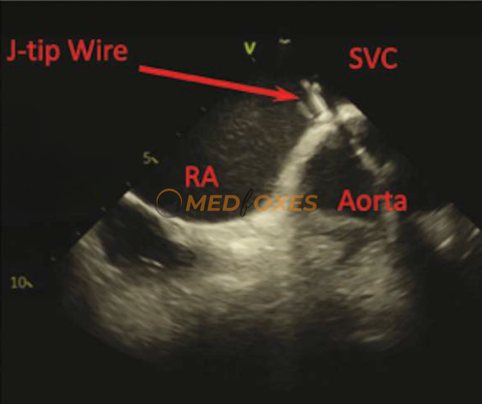
For optimal results, the wire, sheath, and dilator should be advanced into the superior vena cava (SVC) with the assistance of intracardiac echocardiography (ICE) visualisation. The ICE catheter can be positioned in the home view, and a long wire with a J-tip can be advanced through a short femoral sheath into the right atrium (RA). In the majority of cases, the wire will be immediately visible within the RA chamber in this view. (Fig.M2)
The easiest and most secure method is to advance the wire until slight resistance is felt. If the wire is not visible in the home view on intracardiac echocardiography (ICE), slowly rotate the ICE to obtain a 360-degree view. The wire should eventually be visible if it is inside the heart. If resistance is encountered outside the heart, the wire will not be visible, and in that case, retract the wire slightly before advancing it again. This process can be repeated until the wire is finally visible on ICE.
After the wire has been identified, it can be advanced into the superior vena cava (SVC). To visualize the SVC on intracardiac echocardiography (ICE), slightly rotate the ICE in a clockwise direction from the home view until the interatrial septum (IAS) is visible. From this position, a posterior and slight rightward tilt will allow the SVC to be seen.
Techniques to View SVC on ICE
Sufficient posterior and rightward tilt should be applied to obtain a longitudinal view of the SVC, enabling clear imaging of all instruments in a long view. This view should be maintained throughout the pull-down procedure, making it a relatively “hands-off” approach. However, a common challenge encountered is that the ICE catheter is often just floating within the lateral RA, causing the image to be unstable and requiring adjustments periodically
One can improve the stability of the imaging of instruments by advancing the ICE catheter into the SVC. During the dragging process, both the sheath and ICE catheter can be pulled together to maintain a stable view of the dilator tip until it reaches the IAS position. This approach offers the advantage of continuous tracking of the dilator tip with a generally stable view throughout the process. However, it is recommended to have two operators for this approach.
Anatomical Landmarks
Several landmarks along the SVC can help orient the ICE image. Keep in mind that the aortic arch is positioned anterior to the SVC, so when visible, the ICE is anteriorly oriented. The right pulmonary artery branch is located slightly postero-septal to the aortic arch, so when it’s visible, the ICE is usually oriented septally. This is likely the correct orientation for viewing the IAS during the dragging process when the ICE is pulled down. (Fig.M3)

Anatomical Variations: A) A more horizontal relationship exists between the IAS and the aortic root, with the IAS located directly posterior to the aortic root. Hence, rotating the ICE slightly clockwise and counter clockwise is useful to assess this relationship when the sheath is facing the aortic root. B) To achieve a better view in a horizontally oriented anatomy, instead of pulling down the sheath which may lead to an anterior position, it is recommended to rotate the sheath clockwise with a minimal pull to transmit the torque posteriorly. This will bring the IAS into a clear view.
Here are some of the ways that ICE can be used to guide transeptal puncture
Visualize the interatrial septum: ICE can provide clear images of the interatrial septum, allowing the operator to identify the best site for puncture and assess the thickness of the septum to avoid complications such as perforation.
Confirm the position of the sheath: ICE can be used to confirm the position of the sheath as it is advanced through the septum, ensuring that it is properly aligned and avoiding complications such as laceration of the atrial wall.
Monitor for complications: ICE can be used to monitor for complications during transeptal puncture, such as pericardial effusion or thrombus formation, allowing for early intervention if necessary.
Evaluate the success of the puncture: After the puncture is completed, ICE can be used to confirm that the sheath is in the correct location and that there is no evidence of residual shunt or complications.
Optimal Cross-Sectional Imaging of the Interatrial Septum (Fossa Ovalis) for Accurate Guiding and Monitoring of Transeptal Puncture
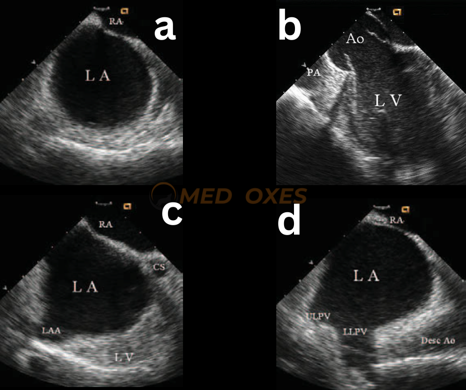
To achieve optimal results, the intracardiac echocardiography (ICE) image should exhibit sufficient space behind the interatrial septum on the left atrial side while accurately identifying adjacent structures. For obtaining a cross-sectional view of the fossa ovalis, placing the ICE transducer near the interatrial septum in the right atrium and clockwise rotation of the catheter can establish the most favourable perspective. (FIG-M4,a)
To obtain the optimal imaging view, the view should first pass through the aortic root (FigM4.b) and then the left atrial appendage orifice (Fig.M4,c). Further clockwise rotation beyond this point will result in imaging of the left pulmonary vein ostia (Fig.M4,d). An optimal view would not include the aortic root structure, as a cross-sectional view that encompasses the aortic root would be too anterior to safely puncture. In cases where the left atrium is enlarged, an ideal cross-sectional view should include the atrial appendage, provided there is sufficient space behind the atrial septum on the left atrial side.
Optimal Site Selection for Transeptal Puncture, Utilising the Best Imaging Techniques, and Accurate Sheath Placement Confirmation in the Left Atrium
For transeptal catheterization, a Brockenbrough needle/stylet and Mullins sheath/dilator unit (or Brockenbrough catheter) are commonly employed. Before insertion, the needle and stylet are positioned within the dilator of the extended vascular sheath so that the needle’s tip is located just inside the dilator. To position the needle/sheath/dilator unit, it is first inserted into the superior vena cava, with pressure recorded through the needle. The needle is then rotated towards the interatrial septum (at 4 o’clock when viewed from below) and gradually withdrawn until the tip is visible under ICE imaging. The unit is adjusted until the tip is positioned against the fossa ovalis. Once in the middle portion of the fossa ovalis, which is the ideal location for transseptal puncture, the unit is advanced gently to reveal the needle tip/dilator tenting of the fossa ovalis. (Figure M5.a).
To puncture the septum, the needle is advanced past the dilator tip. During this step, the proper direction and depth of the puncture can be ascertained by observing the needle tip tenting (Fig M5.b) and the crossing of the septum as the tenting is relieved. As the dilator and sheath are subsequently advanced over the needle and into the left atrium, transient “tenting” of the interatrial septum may again be observed. The successful entry into the left atrium should be confirmed by recording a left atrial pressure waveform. The needle and dilator can then be removed, and the location of the transeptal sheath in the left atrium is confirmed by the observation of echo micro bubbles upon flushing the sheath with saline. (Fig: M5.c)

Conditions of the atrium requiring caution during transeptal catheterization
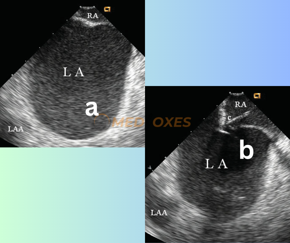
Patients with very large left atrium due to mitral stenosis and/or longstanding atrial fibrillation pose a challenging condition for transeptal catheterization and carry a potential risk of cardiac perforation. These patients also have difficulty with transseptal access close to the center of the septum, as the center of the atrial septum significantly protrudes towards the right. However, ICE imaging can accurately identify the precise location of the fossa ovalis, as depicted in (Fig: M6.a) and guide the transeptal puncture, as demonstrated in (Fig: M6.b) with ease.
Transeptal catheterization in patients with an atrial septal aneurysm, particularly with a normal atrial size, should be approached with caution. ICE imaging can reveal the aneurysm bulging toward the right atrium (Fig: M7a), left atrium, or alternating between the atria, depending on the difference in atrial pressure during the cardiac cycle. The transseptal puncture can be performed in the fossa ovalis where the aneurysm is located. During transseptal puncture, deep tenting and bulging of the aneurysm may be observed, and penetrating through the septum may be challenging (Fig: M7b).

A higher potential risk of inadvertent puncture of adjacent structures may be indicated by less space behind the septum.
In aged patients with cardiac arrhythmias, lipomatous hypertrophy of the atrial septum is frequently observed, which can make transseptal puncture challenging in the thickened section of the septum. However, ICE imaging can readily locate the thinner part of the fossa ovalis that needs to be punctured, thus avoiding the hypertrophied atrial septum and ensuring a successful transseptal puncture.
Reading Suggestions: Cardiac Structures In Intracardiac Echocardiography